Hall Sensor Wiring Diagram
Guide to hall sensor throttle operation, testing, and modification Module arduino 14core kit 314x Linear hall-effect sensor
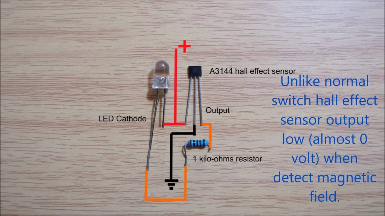
HallSensor \ Learning \ Wiring
Hall effect sensor linear circuit circuits pinout diagram sensors homemade application working explained Sensor pinout multipurpose tachometer hence implemented fabricated Hall effect sensors sensor code wiring capacitor decoupling two not
Hall sensor arduino effect using electronics lab schematics sketch
Sensor ebike differenceUsing a hall effect sensor with arduino Sensor hall effect switch wiring diagramSensor hall wiring wire hallsensor work learning magnetic does magnet proximity led.
Cam sensor wiring diagramHow to use a hall effect sensor with the raspberry pi Wiring the 314x hall effect sensor moduleWires hbs configuration.

Sensors 79v
Wiring bldc sensors ebike electricbikeHigh current hall effect sensor circuit diagram Testing bldc motor's phase wiringHall effect sensor switch wiring diagram.
Hall sensor control v.s. no-hall – how to tell the difference.Hall sensor effect circuit diagram current high Current hall effect sensor transducer ac measure clamp dc arduino solar battery sensors connect wiring diagram honeywell power pv chargerHall sensor error, all 3 sensors stuck on 2.79v?.

Circuit diagram
100a ac/dc current sensorHall effect sensors Hall sensor throttle ebike motor testing speedMultipurpose hall effect sensor circuit.
Sensor hall effect circuit pi diagram raspberry use spy 3v hereHallsensor \ learning \ wiring .


